Welcome to the Austin Seven Friends web site and forum
As announced earlier, this forum with it's respective web address will go offline within the next days!
Please follow the link to our new forum
http://www.austinsevenfriends.co.uk/forum
and make sure, you readjust your link button to the new address!
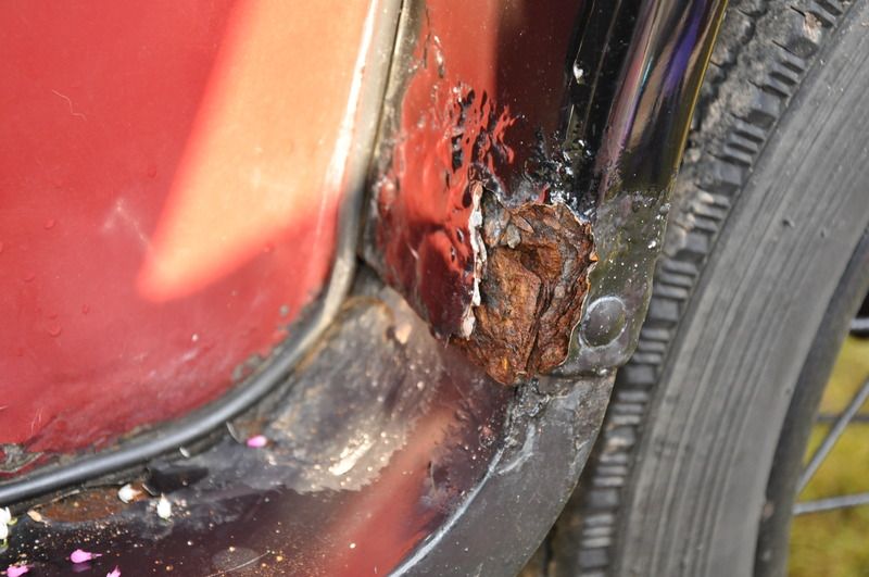
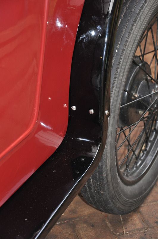
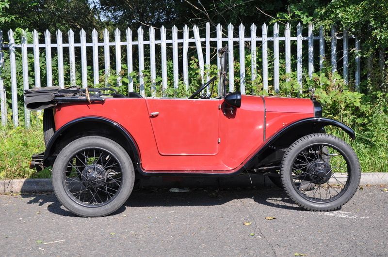
When I first got my Seven I thought that the running board / sills were originals but they didn't look quite right. I realized what the problem was when I saw pictures of AD bodied cars with the sills as Austin had made them:

pic host
My sills had been fabricated with the incorrect ends where they bolt to the rear wings; having right angle bends instead of the radius that matched the body edge:

upload pictures online
So this meant I had to make up the correct radius double flanged edge to weld to the end of the sill along with the top curved edge to correct this. I knew this would be difficult but also knew if I made a forming tool I could make it. I machined the form from half inch aluminum to match the desired dimensions less the thickness of the steel. A thick piece of wood / fiber board was cut to shape to use as a clamp. Two thick strips of aluminum were cut to use as hammer form drifts so as not to mark the steel when working it.

image upload
The next four pics show the sequence in flanging the outer edge of the steel over the form:

free photo hosting

image hosting 12mb

upload png

image sharing sites
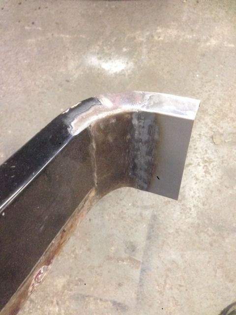
This is what the part looked like after forming on the tool:

how do i print screen
This method can be used to make flanged parts from most metals, but the form toll needs to be hard. I've had success with soft metals using wood forms so it should be possible to do this sort of thing with the tools one has on hand in the average workshop.
I hope this inspires others to have a go at making up the repair pieces they need to restore their Seven.
Cheers,
Stephen
Hi there,
I like the heavy alloy former you created and the clamps to
Make the radius end part piece.
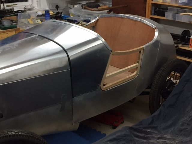
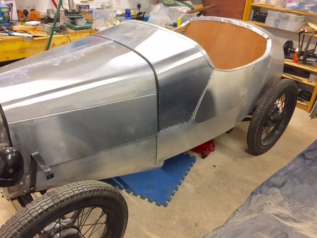
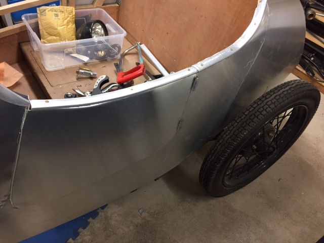
I did something similar last week on the small doors on my GE Cup alloy bodied special.
On fabric Cups the doors are a snug fit in the body side and are edged with fabric covered piping as the draught seal.
I could not see how to replicate this in alloy. So decided to make the alloy door skins oversize to create a flap edge round the door as per 2sester Morris 8's or prewar MG's.
The wooden door frame was made a snug fit and I then edged it with a slim right angled alloy extrusion from B&Q , pinned on with small nails. Easily bent and put in a few judicious hacksaw cuts.
The door skin alloy 16swg was offered up to this and a profile of the perimeter of the outer edge of the extrusion marked on the inside of the door skin.
I then clamped the door skin between two shaped thick plywood sheets that matched the profile I wanted .to fold over.
Then set about the clamped assembly with a hide hammer folding over approx 6mm of the door skin to a right angle.
Then unclamped and further bent the folded edge over a piece of aluminium same thickness as the flange.
I left the top and rear unfolded so I could then slide the door skin on over the extrusion.
Clamped the skin into the door frame and set to with more hammers!
Basically folded over the door skin180 degrees to clip onto the extrusion around 2 sides. The top of the door skin than hammered over the top of the door and nailed on and trimmed. Care taken on the rear edge of the door so it did not foul anything when opened.
I seem to have lost the knack of photos again so will send a photo or two to Ruairidh who I hope will kindly repost.
Not perfect but pretty pleased with my first foray into alloy coach building...
Regards
Bill G
Ps this posting for anoraks only !
Location: Scottish Border
Nice clear pic of the late 26 AD, never seen that back to front view of the pic in Wyatt which 'is' the right way around. Where did you get it Stephen?
Rivet counters note advance and retard levers shown at twelve and six o'clock!
BTW nice job Stephen. Ian M
Location: Bristol
Reading my post again,I'm not suggesting all the levers were fitted that way but original Austin photos seem to show that the position wasn't consistent. Ian
Location: Bristol
Thank you for the kind offer Ruairdh. I have the radius all worked out now and the parts made. The parts will be welded on after the floor is made so that they can be made to fit.
Stephen
Thank you Bill, Sounds like you have also figured out a way around a problem. Nice to hear.
Stephen
Hi Ian,
the pic I used was the one you are familiar with only photo shopped to show the "mirror" image. I did this so the comparison between my existing sill and the factory one could be more easily compared. Thank you for the compliment.
Stephen
Thanks Stephen, presumably you also were able to enhance the clarity, very clever shows what can be one if you know how. Ian M
Location: Bristol
Very nice job, but when I was in business & making & repairing running boards - in quantity! - I found the ends too time-consuming (thus costly) to do similarly, so thereafter fabricated the curved bits. With new boards all it required was to weld on a shaped side-piece to the extra length (which I had curved) to the flat section either end. This meant only a quick weld along the top outer edges of the curve, plus a quick weld across the board if making a complete new end to an existing board. Then with a proper bending tool ( a vice grip would be okay) shaped the 1/2" flange underneath. If the latter is found to be difficult, the flange can also be welded on. And writing of under-side flanges reminds me - if you have a '23 model, the running-boards do not have a flat flange underneath, but instead the flat flanges are rolled around 18" wire. Hope this alternative helps others to choose the most convenient for them. Cheers, Bill
Location: Euroa, Australia
Stephen and others - a rider to the above. I recall now that I bent the small 1/2" flange to the side-piece Before welding to the board. Much easier than doing it on the completed piece. But a question to Stephen - (not a criticism) - have you checked your completed board alongside an original real one? It may be the photos, but to me it seems your end piece is too semi-circular. In real life, the curve requires some "straightening out" on the vertical section so that it will fit easily up under the descending wing. Ruairidh's photo of a completed board seems right to me. Hope I'm wrong with my view of your good work, only trying to help. Good Luck with it. Cheers, Bill
Location: Euroa, Australia
Hi Bill, the radius of the piece was made to match the lower rear edge of the body. I made the circular bit oversize so it could be trimmed to give what ever degree of curvature is required to mate with the rear wing when offered up to it. This will be determined once the body floor is finished and the sill can be attached to the underside of the body flange. Should work I think.
Thanks for your input and concern about the shape.
Stephen
Nice work. I like the idea of doing That kind of work. I am in the process or learning to tig weld
Location: Ireland
It's suddenly dawned on me that the sill should have a wired lower edge from where it attached to the front wing back and up to the rear wing also ?
Can anyone confirm this for me please ?
Thanks.
Stephen
Stephen - I would be interested if some-one comes forward to the contrary, but of all the mudguards I repaired it was only the 1923 model that had the wire, all others had a half-inch flange, see my item above. Cheers, Bill
P.S. It's also interesting that when I typed 1 slash 2 the computer immediately altered it to read 12 - tried to alter it several times, no go. Thus the full spelling. BS
Location: Euroa, Australia.
Thanks for your insight Bill. On my particular car both the front and rear wings have wired edges, which is why I suddenly wondered if the sills should be too.
Stephen
