Welcome to the Austin Seven Friends web site and forum
As announced earlier, this forum with it's respective web address will go offline within the next days!
Please follow the link to our new forum
http://www.austinsevenfriends.co.uk/forum
and make sure, you readjust your link button to the new address!
I need to do the Knig Pins on my 1934 Austin Ruby, does anyone have any tips.
We were thinking of taking the whole front end away from the car to do the job (along with some other maint), I have heard these can be difficult to do
I'd suggest you take off the front end and strip it because very rarely will it be your kingpins that are worn (unless they've been made of some dud material), it'll be the axle eyes that have belled out. You will need to weld around the eyes to "shrink" them back into some sort of shape (a build up of weld around the area also makes stronger for future use), then you'll have to ream out the bore to ensure it's a round (preferably) 1/2" again, then you need to face off the top and bottom to ensure everything's back to near standard. We use a jig to ensure holes are vertical, in line with each other etc, but you probably don't have access to this sort of thing. Even reputable manufacturers in the past have turned out kingpins that have been hardened incorrectly etc, the pins breaking at inconvenient and dangerous times, so be careful with replacements. Suggest someone reliable like Seven Workshop in England as a good source. If all of the above is done you'll readily see how difficult if not impossible it is to do properly on the car. Your life could be in the hands of how well your front end is done. Good Luck, Bill in Oz
The following is an articel that i wrote for the A7 club magazine "Baby Torque" 12 mths ago specific to how I repaired my axel. Some of the articlae is Parochial so If not interseted in thewaffling of an Western Australian just skip it, The drawings are available if you want them off line. Regards Doug
When considering this article I wasn’t sure what to call it, was it to be Doug’s dilemma or Doug’s delight! The folly has still not been resolved, so I will settle on both, as from a dilemma it did become a delight. I have to presume it is about now you are starting to wonder what I am waffling on about. It’s nothing more than an Austin Seven front end and the journey to repair it. Frankly the story is enough to make a saint waffle.
This chronicle actually and unwittingly began when I trailered my Chummy as a static display to the Brookton Old Engine Show. On the Saturday morning after all the attendees had lined up the bonnets of their Austins like tin soldiers on the parade ground, there was an interest shown in my gorgeous little red Chummy “Jane.” It was then the scrutinizers descended on Jane without compassion. These adjudicators heckled and ridiculed her braking system with unbridled hilarity and the associated components to the degree her battery went flat with shame, coupled with elevated anxiety and post ignition trauma evident. This focus was due to the components installed by the previous owner as there were lengths of chain, pulleys, (originally used as a component for rolling up a blind), a length of angle iron of dubious origins, weird bowden cables affixed to the radius rods at obscure angles, and sundry gutter bolts holding it all together; simply, it wasn’t her fault. Nor was it fair that she was the isocentre of mockery, even today her head lights keep on misting up with the shame of it all. In an effort to resolve her anxiety I commissioned an Austin Seven ignitionoligist with his little green book to counsel, console and reassure her. It took a good number of visits of the eminently qualified ignitionoligist, in the form of my 12 year old grandson Max, who with his reverent compassion had a breakthrough, and Jane finally acquiesced allowing me to jack the front wheels up to remove the universal excrement from the brake assembly.
When I did this regrettably a sordid tale unfolded, as the wheels on each side dropped inward at least 40mm! I simply could not believe what I was seeing. In my opinion the braking system was conceived through smoking that funny stuff on a magical mystery tour, but the integrity of the king pin assembly and associated components was retrieved from one of the lands of the Faraway Tree. How anyone could reassemble a front end with absolutely dangerously unserviceable components defies logic and explanation.
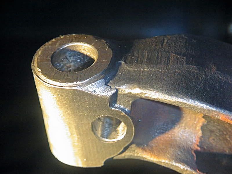
I will endeavor explain: One king pin was so badly worn the previous owner had built the pin up with weld and then cleaned it up with hand grinder. The king pin eye in the end of the axle on one side was so excessively worn that in an effort to over come this, the concave style cotter was ground to resemble a tapered pin with a larger nut under the 5/16 nut to give the taper more follow through.
The radius rod on the passenger side had a bend in it of about 60mm over all with a cheap Zenith mild steel bolt through the ball joint holding the assembly together. They were the good bits!
In removing the axel I then discovered the ball joints of the drag link also had been welded and hand ground as with the brake levers. The brake cams had over 2mm clearance in the bushes with the cam apex almost worn to a generated radius.
But wait there is more; the front wheel hub nuts had wire through instead of split pins this actually applied to every castellated nut, no matter where it was. The spring shackle bushes were worn right through the bronze and had actually worn the bush housing bore and the axle facing. And then, and then, there was the track rod ends, the bushes so worn there was only some colour of bronze in the bushing bores with the pins, oh forget it!
The shock absorber has been assembled incorrectly and affixed to the axle with cheap mild steel bolts with bits of water pipe cut as spacers between it and the axle.
I recall it was at this point I really felt low as I had bought this car with the understanding that it was fully restored, buyer beware. After a couple of sleepless nights and in my nocturnal hours I decided to ring Tito who is in charge of the spares shed (my latest best friend) to see if he had another axel assembly that was in better condition. After some horse trading John Bannister kindly volunteered to deliver the replacement axle to me. In stripping this axle I soon realised while it was better than mine, it was only marginally so.
I was left with no recourse but to roll up the sleeves and repair the axle and components as all avenues for any other approach had been exhausted.
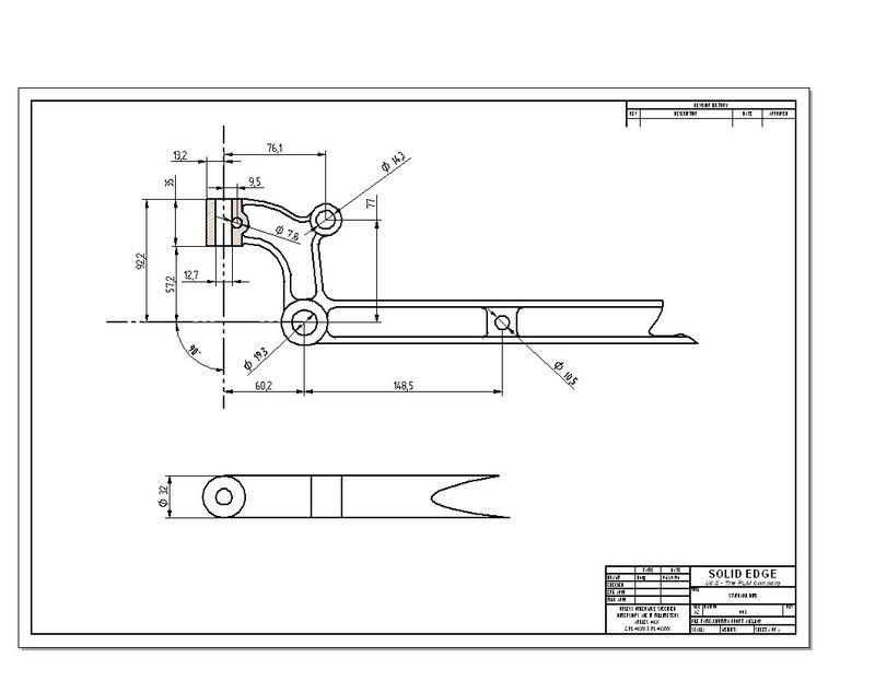
Before I tackle any job of this magnitude I like to have a drawing so if anything should go pear shaped I have a reference. Further, if one is going to do any machining it is essential to have finish dimensions to machine to. (See drawings fig 1 and 2)
It was at this point I asked for advice from anyone who stood still for more than two minutes on what established repairers had done in refurbishing the king pin eye of these axels, to this I was offered sound advice from all I asked. (I would like to extend a special thanks to all who were sympathetic and had assisted with this information) Armed with this advice, I went away and mulled it over considering and reflecting on every angle that would cause me concern. I even went on the net and searched around reading commercial repairers methods. None of these sat comfortable with me, given the damage to the axel as it wasn’t just the king pin bore. It was at this point I decided as I now have two axels I will have a go at repairing the original axle as it was the worst of the two by far, and if I manage to destroy the original, I could fall back on axle number two.
Having reached this paramount decision albeit with trepidation, the next was to establish how I was to undertake this repair. Irrespective of the machining process the king pin eye had to be fully welded not only inside but the outside including top and bottom.
In setting up a contingency plan I deduced I had to weld the outside first using the bore for the king as my datum; everything had to be built up central to that.
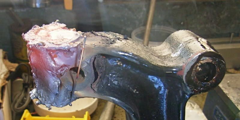
Knowing that mild steel MIG welding wire will not adhere to copper during the welding process, I manufactured a jig in copper with a centralising spigot ½” diameter and 1¼” OD (see photo) This was inserted into the king pin hole and clamped into position ready for welding.
The first step was to weld the facing ends of the axle so as to build up a collar at each end. When this was done the area lying between the now enlarged ends was filled with weld perhaps a little excessively, but when one wants to have material to machine to size it is better to have too much than not enough as the area of inadequate material would have to be re-welded.
After I did this I allowed the weld to cool off naturally overnight so as not to introduce any hard spots. The next day I drilled the king pin hole out to 5/8” diameter, in reflection, I now consider this a mistake as the hole should have been drilled out before welding. In doing this I could have welded the king pin bore hole up while the end was still hot from welding the outside.
The next phase was to machine a copper plug which would fit down the king pin bore that was half the depth of the hole. This plug had a substantial head on it so as to facilitate easy removal after welding. I actually thought the plug would lock in the hole due to the welding so I was prepared to drill it out. It transpired that was not necessary as there was no trouble in removing it at all. Now the king pin bores were ready for welding I considered it necessary to preheat the end up again to enable a deep penetration of the weld, this is the reason for my previous comment. If I had continued with the welding process the preheating of the axle would not have been necessary.
Welding down a 5/8” diameter hole is not easy! The method I employed for doing this was to start the ark, and by holding the torch on an angle with an extended length of wire protruding from the welding handpiece nozzle. I found the hole filled with Argo shield gas and despite the wire protruding further than what is recommended, the arc burnt very convincingly. In adopting this method, I moved my wrist in a circular pattern with the ark focussed at the parent metal. In doing this I could see a very deep penetration of the weld and the molten metal started to swirl just like water going down a drain. It was also at this point that I noticed the molten metal was so hot that it was cutting a swathe in the bore also as it filled the hole. The metal did not oxidise as it had the Argo shield gas insulating it from the atmosphere.
While I haven’t mentioned it, I have to assume you appreciate I was wearing leather protective welding gloves and apron. The heat generated was so intense that I have no doubt that I would have finished up with either 1st or 2nd degree burns, not only from the infrared radiated heat but from the ultraviolet rays radiating from the arc. It is also essential to protect your neck, I respect that most would consider that statement obvious. Notwithstanding I actually forgot to do it once and I paid the price, absolute agony for a week. As an additional cautionary comment, all arc welders no matter what their configuration emit uvB that can cause somatic skin cancer. Further, there is a very high probability of incidence of malignant Melanoma, this being the worst of all the skin cancers. Please, for your own sake, ensure that all safety precautions are embraced.
When completing the first stage of the welding process I removed the copper plug and turned the axel over and repeated the same welding procedure in the opposite side half. By this stage I was gaining confidence as the methodology was working quite convincingly. Now the bores were fully welded to my satisfaction I reduced the welding machine current and welded the top and bottom of the axle king pin eye for about 5-6mm.
One end now was completed and while still seriously red hot one could see that it was a good job with no blow holes and plenty of metal to machine off. Turning to the other end, the same procedure was adopted and while the same precautions were embraced this end didn’t seem to take as long to weld up. The axel was once again allowed to cool off over night. The next day looking more closely with critical eyes I was still feeling quite confident with the results. I acknowledge the mass of weld on the ends didn’t look very pretty yet I knew it was going to machine up fine.
The next link in the process was to machine the welds back to the credible dimensions as per the drawing. This was carried out in the turret milling machine, and as previously stated, I had collated a contingency plan on how this was to be done. I am of the sincere opinion that it essential that a plan of progress must be established before any job is addressed. I will bet if you don’t, a situation will crop up that is going to cause grief and loss of time.
I remember my bygone lecturer stating “You may not have time to pull a plan together with the first attempt but you always manage to find time with the next attempt to repair the stuff up.” He also said “A man who never made a mistake never made anything at all” A clever bloke.
In machining a component in any configuration a datum is essential, for this reference I used the two radius rod bolt holes. I reflected on how the Austin factory may have machined and to this end the only way I could see the axle being held during machining with any conviction was with these two holes. Having resolved this essential prerequisite I inserted a length of round stock 3/4 “ diameter through each hole that was supported by two “V” blocks at each end with clamps holding the axel in the correct parallel position to the table references. Once satisfied the axle was square to the axis I machined as the first process, the width of the axel using the cotter key faces as my finish size. Refereeing to the drawing, I then machined the top back to size so now I had the top and both sides on each end of the axel machined to specification, and square to each other.
With engineers blue marking stain applied I measured the centre of the axle and carefully marked a centre line. Using a wobble pin that locates centres, I went back to the ¾ stock that was holding the axel in the “V” blocks and picked up that centre. I now wound the table along corresponding to the dimension on the drawing. Still using the wobble pin I then picked up the machined edge and moved the right angle axis half the distance that corresponded with the centre line previously marked. The scribed mark centre line was for reassurance only.
Having established the exact position of the king pin bore, I started the machining process by using a centre drill and spot drilled the hole position. This followed with a pilot drill ¼”diameter, opening to 7 /16” diameter. After these holes were drilled I enlarged the hole further using a 12mm long series slot drill followed by a 12.5mm slot drill. The reason for doing this is that , slot drills cut on the front of their cutting edge, the advantage being they will not follow the drilled hole but cut to the exact established centre. Additionally, I wanted to ream the hole to the finished diameter and the 12.5mm slot drill gave me 10tho to clean up to size. However the slot drill cut slightly over size and measuring the new king pin I discovered that it was 1tho undersize that is to say.499” as opposed to .500” leaving me a total of 6tho to finish off. I used a fixed diameter machine reamer that was .498” in diameter, by coincidence, or my Scottish heritage to the fore, this worn reamer I had kept for years, I could never bring myself to throw it away. At the slowest spindle rpm speed the reamer cut the hole perfectly and when measured it was spot on .498”.
Feeling quite satisfied with the results, next came the finish machining the circumference or radius of the top. I acknowledge I really didn’t have to do that this operation, but when I pad welded the top the circumference of the weld was raggy and didn’t look too flash. To make the top circular I used the boring head with the cutter facing inward instead of outward. With my boring head I have a facing option that will face to a stop and trip the feed out, so that is exactly what I did, I set the stops and engaged the feed of the head and allowed the machine to do the rest. This end of the axle was now completed as far as I could go, so the other end was machined in the exact same manner as described. In having done both king pin bores I removed the axel from the set up. Inverting the axle and machined the underside to length using an end mill.
The final machining procedure was to machine the radius on the end of the axle for this I used a rotary table. To facilitate this I required a mandrel to hold the axel during the machining. Searching through the scrap bin a piece of off-cut round bar about 50mm diameter was selected. This was faced on both ends in the lathe where I also I drilled and tapped on centre a 1/2” UNF hole. When done, the mandrel was held in the four jaw chuck fastened to the rotary table and using a dial indicator the mandrel was adjusted to run true to the table centre. I then bolted the axel to the mandrel with a 1/2” bolt ensuring that it was done up very tight. With the axle now held on the rotary table I proceeded to machine the radius carefully with small depth cuts. This method was repeated until a generated radius of equal proportions to the king pin centre was evident. Having completed this end, the axle was removed and the other end was bolted in place and machined in the same manner as the previous end. The results were very pleasing indeed and there was only one small job left to do being the cotter key holes that I machined out with a slot drill.
The final job was to remove the sharp edges and let the hard work of assembly begin!! Or was the hard work this article?
Yours in Austineering
Doug Baker
Doug,
I will get around to posting up your photos, sorry not to have done it yet, time etc.....
If you are UK based and need your axle eyes repaired etc. then check out:
www.vintageaustinservices.co.uk
Hope this helps
Cheers
Ruairidh
Thanks so much for the advice, I plan to tackle this job in the next few weeks
OK I have the front axle out.
Should the axle be dead straight or does it have it have a slight bend.
This one is slighty bent and I'm not sure that it should be.
Any help please