Welcome to the Austin Seven Friends web site and forum

As announced earlier, this forum with it's respective web address will go offline within the next days!
Please follow the link to our new forum

http://www.austinsevenfriends.co.uk/forum

and make sure, you readjust your link button to the new address!

Welcome Austin seven Friends
This Forum is Locked
Author
Comment
SM5 Internals

I am repairing a SM5 switchboard and am not quite sure about the exact shape of the spring with little rollers on it, mine appears to have been bent out of shape. Does any one have a picture of a good one?

Location: Near M1 Jtn 28

Re: SM5 Internals

Brian,

Sorry- no picture, I thought one of the wiring diagrams showed it but I cannot find one.
This is the interesting Lucas summer 1/2 charge winter full charge 'switch' which works with both the charge rate and the headlight teardrop switches on the SM5 panel to bypass the half charge resistance in the field winding.
Because of the relatively tiny dynamo (generator) charge rate, I have connected the two terminals at the dynamo thus producing full charge at all times rendering the SM5 'switch' redundant.

Tony.

Location: Malvern, Melbourne.

Re: SM5 Internals

Managed to work out the configuration for myself but this may assist someone else.
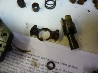
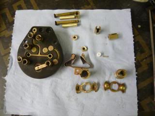
I caption the pictures but the captions have disappeared! The first picture shows a broken selector, the second with both switches in the OFF position, the third all the parts repaired and cleaned and the last one is of both switches in the ON position.
Broken SM5 selector. photo P1100166_zpsf52c5523.jpg


SM5 in both OFF position. photo P1100168_zpsd3c72a26.jpg

SM5 parts cleaned, Note double spring part with damage. photo P1100167_zps150fcdac.jpg

SM5 in both ON position photo P1100169_zpsdcff297d.jpg

Location: Near M1 Jtn 28

Re: SM5 Internals

Well done, Brian. As they say down the west country "proper job!". May I please post those pictures on my "Bits and Bobs" Pinterest page.??


Test Image.

Ian Mc.

Location: Shropshire

Re: SM5 Internals

No problem Ian be my guest. I also have some other pictures that I could send to you for you to pick out ones that may be useful.

Location: Near M1 Jtn 28

Re: SM5 Internals

I would appreciate that Brian, thank you.

Ian Mc.

Location: Shropshire

Re: SM5 Internals

PLEASE NOTE THAT I HAVE MADE AN ERROR IN ASSEMBLY AND WILL ADD NEW PICTURES TO CORRECT THIS (when I have worked out what the problem is)

Location: Near Jtn 28 On M1

Re: SM5 Internals

Brian Hutchings
PLEASE NOTE THAT I HAVE MADE AN ERROR IN ASSEMBLY AND WILL ADD NEW PICTURES TO CORRECT THIS (when I have worked out what the problem is)


Problem solved (with thanks to Ian McGowan)
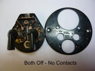
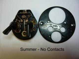
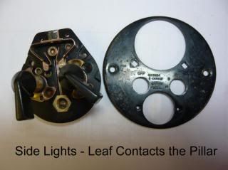
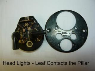
The parts that are dimpled were wrongly assembled meaning that the short part of the spring contacts did not touch the short pillar.

href="http://s157.photobucket.com/user/BrianHutchings/media/1_zpsf12af2fa.jpg.html" target="_blank">SM5 1 photo 1_zpsf12af2fa.jpg
SM5 2 photo 2_zps1befd11b.jpg
SM5 3 photo 3_zps98edccf5.jpg
SM5 4 photo 4_zps228990a4.jpg
href="http://s157.photobucket.com/user/BrianHutchings/media/5_zps09a829e3.jpg.html" target="_blank">SM5 5 photo 5_zps09a829e3.jpg

Location: Near M1 Jtn 28

Re: SM5 Internals

Brian,

I don't think the leaf should contact the pillar with the side lights on only the headlights.

Tony.

Location: Malvern, Melbourne.

Re: SM5 Internals

Sorry Tony, I disagree. See quote from 1932 Handbook 715F below.

"Switch Positions
Each switch has three positions. Left hand switch (1) "OFF"
position-dynamo not charging and ignition off. (2) "Summer 1/2
Charge" position-ignition operating and dynamo charging with
half its normal output. (3) "Winter Full C" position-ignition
operating and dynamo charging with its full output. Right hand
.witch (I) "OFF" position-all lamps off. (2) "S" position headlamps
dim and tail lamp. (3) "H" position-headlamps bright,
and tail lamp. Switching on lamps automatically puts the dynamo
on full charge.

Ammeter
The centre zero ammeter indicates
the rate at which the battery is being
charged or discharged under all conditions.
For instance, suppose 2
amperes are consumed when the dim
lamps and tail lamp are switched on,
and that the ignition coil takes 2
amperes, then if the dynamo is
generating 7 amperes the meter will
show 3 amperes on the charge side of
the scale. This is the current in excess
of the lamp and ignition load that
is available for charging purposes."


Ian Mc.

Location: Shropshire

Re: SM5 Internals

Ian,

I have always taken this to mean when the full 'headlamps' are lit the dynamo is put to winter Charge.
As far as I know the Lucas SM5 cars were fitted with Lucas 7" headlamps which use a single contact 21 watt 'headlamp' bulb and a single contact 5 watt dim or 'park' bulb, which was lit on the dim setting.
The ammeter charging description I assumed would apply with the charge switch set at Winter, the readings mentioned for the dim setting are 3 amps for headlamps on dim or 'park' plus the tail lamp, with dynamo at 7 amps.
The 1931 Handbook bulb descriptions are headlamp- BAS No 1, dim- BAS No 8 and tail- BAS No 8 -which I have taken to be BA15S 21 W and BA15S 5 W respectively.

But as occasionally happens I could be wrong

Location: Malvern, Melbourne.

Re: SM5 Internals

Hmm, a fair few assumptions there Tony. I won't be so bold as to state definitively that you are wrong but, I do believe that the intention was that the SM5 provided full dynamo output when ANY lighting was switched on.Indeed I am of the view that a careful study of the "cam profile" of the dimpled brass switch wafer, which engages with the rollers controlling the actuation of the "full charge" switching supports this opinion.

However, as you said, I could be wrong!! I was once wrong, when I thought I had made a mistake but actually hadn't.

Ian Mc.

Location: Shropshire

Re: SM5 Internals

Please note that Brians photos of the internals of the SM5 switch panel are now posted on the "Bits and Bobs" pInterest board (see second "sticky post" at top of forum page)

Ian Mc.

Location: Shropshire

Re: SM5 Internals

Ian,

Many thanks- I do like the Bits and Bobs pictures
And of course thank you to R and all the other posters for the excellent and most accessible collection showing details of the various Austin Seven models !!

Tony.

Location: Malvern, Melbourne, Australia.